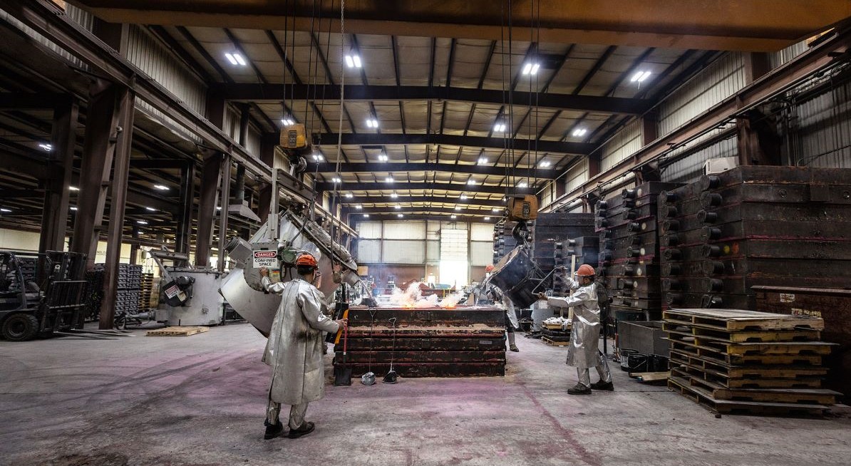
Exploring the process behind the product; learn more about how thermoforming tools are created.
Many times, the process is just as important as the product. An intricate design process is something we pride ourselves on here at KFI. One of the important steps in that process is tool making.
Our thermoforming tools are made by sand casting while others are created as machined billet tools. The big difference is sand casted tools require a pattern for the foundry process, while machined billet tools do not. All tooling requires the use of a CAD model to create the tool with a temperature control system added as part of the machining process. For this blog, we will focus on sand-casted tools, as these are what KFI uses.
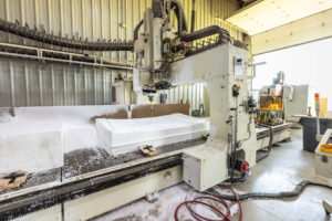
To kick off the process a pattern is created by a 3D printing or CNC cutting of a material like wood, foam, or a synthetic REN. This pattern is then used to create a void in the sand in the foundry. Once the pattern arrives at the foundry the forming surface of the pattern is put in a foundry flask. A foundry flask is a frame that holds the sand. The pattern is then covered with a mix of silica sand, binder, and a catalyst that work together to harden and create a negative impression of the pattern; this process is called ramming.
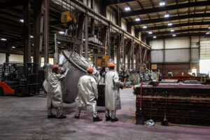
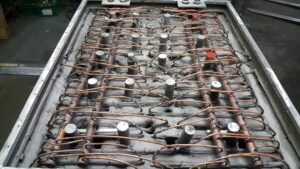
After ramming is complete, the pattern is then taken out of the hardened sand and a layer of 3/8” to 1/2” of clay is applied to the sand surface. Once the entire surface is covered with clay, stainless steel water lines are then applied on top of the clay. Another foundry flask is placed on top and filled with the same mixture of silica sand, binder, and catalyst as before. Once this hardens the top flask is removed along with the clay. The reaming void between the two flasks is where the molten aluminum is poured to create the tool-forming surface.
At this point the tool is ground, sanded, and polished to remove rough spots. At this point in the process is where KFI differentiates itself from other thermoformers. Our temperature control system is fabricated to produce uniformed tool surfaces, “The internal temperature control system is constructed and laid out to optimize tool creation. Our system assures that we can achieve a high cycle rate along with a uniform temperature-controlled forming surface,” Tooling Engineer, Steve Gardiner said.
Small vacuum holes are then drilled through the entire aluminum tool to make it functional for forming the plastic part on the thermoformer. The entire surface of the tool is then sandblasted to give it a uniform texture and assure uniform vacuum dispersion. After this, a bottom plate is fabricated to create a sealed chamber for the forming process, and the tools are sent to our KFI plants.
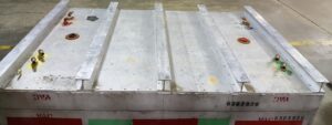
Although this only captures an overview of this process, our tooling and design engineers have extensive knowledge and industry experience in creating, optimizing, and evaluating thermforming tools. If you would like to speak with any of our design, engineering, or sales teams about thermoforming tools feel free to contact us today!
